
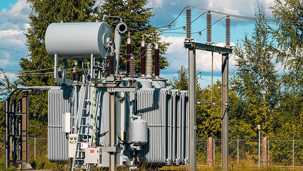
Regular insulation testing is critical for preventing equipment breakdowns, unplanned downtime, and electrical hazards—especially in motors and transformers, which are often the backbone of industrial and commercial power systems. A megohmmeter (sometimes called a “megger”) is the go-to instrument for measuring insulation resistance. In this guide, we’ll walk through the step-by-step process of testing motor and transformer insulation with a megohmmeter, ensuring you gather accurate data that helps safeguard your critical assets.
1. Why Insulation Testing Matters for Motors and Transformers
- Prevent Unexpected Failures
- Worn or damaged insulation can lead to short circuits, overheating, or catastrophic failures, all of which can disrupt operations and incur high repair costs.
- Extend Equipment Life
- Early detection of insulation deterioration allows for prompt maintenance or replacement, prolonging the lifespan of motors and transformers.
- Ensure Safety
- High-voltage circuits pose shock hazards and fire risks if insulation is compromised. Testing prevents accidents and maintains a safe working environment.
2. Gather Essential Tools and Safety Gear
- Megohmmeter (Insulation Tester)
- Choose a model rated for the voltage class of the motor or transformer (commonly 500 V, 1000 V, 5 kV, or more for large industrial applications).
- Multimeter or Voltage Tester
- Verify circuits are de-energized before connecting the megohmmeter.
- Insulated Gloves and Safety Glasses
- Protect against accidental arcing or electric shock.
- Lockout/Tagout (LOTO) Devices
- Secure and label the circuit to prevent unexpected re-energization.
Safety Tip: Always follow NFPA 70E or local electrical safety standards when working on high-voltage equipment.
3. De-Energize and Discharge the Equipment
- Switch Off Power
- Turn off the main supply to the motor or transformer at the circuit breaker or switchgear.
- Lockout/Tagout
- Attach a lock and visible tag to ensure no one restores power mid-test.
- Discharge Stored Energy
- Motors and transformers can store charge in windings. Use built-in discharge functions on your tester or manually discharge using a resistor or grounding cable.
Important: Use a multimeter to confirm the voltage is truly zero before connecting your megohmmeter.
4. Access Motor or Transformer Terminals
For Motors
- Terminal Box: Open the terminal box to expose phase leads (U, V, W).
- Separate Winding Leads: If a motor has multiple winding configurations (e.g., star/delta), ensure the connections are accessible for individual testing.
For Transformers
- Primary and Secondary Terminals: Remove any jumpers or bus connections, if applicable, to test each winding separately.
- Neutral or Ground Points: Identify the neutral or grounding points to measure insulation to ground.
Tip: Document or label all connections before disconnecting wires to ensure correct reassembly.
5. Select the Correct Test Voltage
- Consult Manufacturer Guidelines
- Motor datasheets or transformer nameplates often specify recommended insulation test voltages.
- Typical Values
- Low-voltage motors or transformers (up to 1000 V) often use 500 V or 1000 V.
- High-voltage motors and power transformers could require 5 kV, 10 kV, or specialized test voltages.
- Avoid Overvoltage
- Using a test voltage higher than recommended can stress or damage existing insulation.
6. Perform the Insulation Resistance Test
- Connect the Megohmmeter Leads
- Line Lead (L): Attach to one phase or winding terminal.
- Earth/Ground Lead (E): Attach to a known ground point or the transformer tank/motor frame.
- Start the Test
- Press the “TEST” button (digital megger) or crank the handle (analog). Allow the reading to stabilize.
- Test Each Phase/Winding
- For motors, measure insulation between each winding (U-V, V-W, W-U) and to ground (U-E, V-E, W-E).
- For transformers, measure HV windings to ground, LV windings to ground, and between windings if accessible.
- Record the Readings
- Note the megohms (MΩ) or gigaohms (GΩ) displayed. A higher value typically indicates better insulation.
7. Advanced Diagnostic Techniques
Polarization Index (PI)
- Definition: The ratio of the 10-minute reading to the 1-minute reading.
- Interpretation: Values >2 generally indicate good insulation. Low or decreasing PI suggests moisture or contamination in the windings.
Dielectric Absorption Ratio (DAR)
- Definition: The ratio of the 60-second reading to the 30-second reading.
- Interpretation: A DAR >1.5 is typically healthy; <1.0 could signal severe issues.
Note: These extended tests help spot latent moisture or degradation that short tests might miss.
8. Interpret Your Results
- Compare to Manufacturer or IEEE Standards
- Many standards (like IEEE 43) outline minimum acceptable insulation resistance for motors or transformers.
- Consider Temperature
- Insulation resistance declines as temperature rises. Apply correction factors if the motor or transformer is hot.
- Look for Trends Over Time
- Repeated tests at regular intervals help detect gradual degradation or moisture ingress before it leads to failure.
9. Discharge and Reconnect
- Discharge the Winding
- Wait for the megohmmeter’s auto-discharge or use a resistor/ground lead. High-capacitance windings can retain dangerous voltage.
- Restore Connections
- Reconnect jumpers, bus bars, or terminal leads as per the original wiring scheme.
- Remove Lockout/Tagout
- Once testing is complete, remove LOTO devices and restore power safely.
10. Keep a Testing Log
- Record Each Reading
- Log the date, equipment ID, test voltage, insulation value, and ambient temperature.
- Track Trends
- Watch for a decrease in insulation resistance over multiple tests, indicating early signs of insulation breakdown.
- Schedule Maintenance
- Use your logs to plan maintenance or thorough cleaning of windings if resistance starts drifting below recommended thresholds.
Final Thoughts
Testing motors and transformers with a megohmmeter is one of the most effective ways to ensure electrical integrity and avoid costly breakdowns. By selecting the right test voltage, following a clear procedure, and carefully recording your measurements, you’ll gain invaluable insights into insulation health—allowing you to act proactively rather than reactively.
Always remember that high-voltage testing carries risks. If you’re ever uncertain about your test setup or the condition of your equipment, consult a qualified electrical engineer or maintenance professional. Proper insulation testing ensures not only peak performance but also the long-term reliability and safety of your critical electrical assets.

 Tibetan
  English
  German
  Spanish
  French
  Portuguese
  Vietnamese
  Afrikaans
  Amharic
  Arabic
  Aragonese
  Moroccan Arabic
  Assamese
  Azerbaijani
  South Azerbaijani
  Belarusian
  Bulgarian
  Bengali
  Bosnian
  Catalan
  Czech
Czech  Danish
  Welsh
Welsh  Lower Sorbian
  Dzongkha
  Greek
Greek  Esperanto
  Estonian
  Basque
  Finnish
  Indonesian
  Italian
  Malayalam
  Latvian
  Panjabi
  Romanian
  Slovenian
  Russian