
A transformer is a stationary electrical device, classified as a type of motor with zero rotational speed. When a power transformer operates within a system, it transmits electrical energy from its primary side to the secondary side through electromagnetic energy conversion, simultaneously stepping up or stepping down the voltage as required for power transmission and distribution. Therefore, it plays a crucial role in the entire process of electrical energy production, transmission, and distribution. In the entire power system, the capacity of transformers is typically more than three times that of the generator capacity.
When a transformer changes the voltage, it adjusts the voltage and current on its secondary side relative to the primary side while maintaining the same frequency. Due to the conservation of energy, the current and voltage changes between the secondary and primary sides are inverse, meaning that when the voltage on one side of the circuit increases, the current on that side must decrease. A transformer does not, and cannot, increase or decrease the “amount” of electrical energy. During the power conversion process, the transformer itself consumes a certain amount of energy, so the total energy input to the transformer equals the output energy plus the energy consumed by the transformer during operation. Since transformers have no rotating parts, there are no mechanical losses during operation, and due to numerous energy-saving measures in the design, structure, and manufacturing of new products, their operational efficiency is very high. Typically, the efficiency of small to medium-sized transformers is no less than 95%, and the efficiency of large-capacity transformers can exceed 98%.
1. Classification and Working Principle of Power Transformers
(a) Classification of Power Transformers
Power transformers can be classified into the following categories based on their use and structural characteristics:
1. By Purpose:
- Step-up Transformer: Increases the voltage from low to high, allowing power to be transmitted over long distances through transmission lines.
- Step-down Transformer: Reduces the voltage from high to low, supplying power to nearby or relatively close loads via distribution lines.
2. By Phase Number:
- Single-phase Transformer
- Three-phase Transformer
3. By Winding:
- Single-winding Transformer: Also known as an autotransformer, which has two levels of voltage.
- Double-winding Transformer
- Three-winding Transformer
4. By Winding Material:
- Copper Winding Transformer
- Aluminum Winding Transformer
5. By Voltage Regulation Method:
- Off-load Tap Changing Transformer
- On-load Tap Changing Transformer
6. By Cooling Medium and Method:
- Oil-immersed Transformer: Typically cooled by natural cooling, air cooling (with fans installed on radiators), or forced air cooling (which includes an oil pump to promote oil circulation). Additionally, large transformers may use forced oil circulation with air cooling or forced oil circulation with water cooling.
- Dry-type Transformer: The winding is placed in a gaseous medium (air or sulfur hexafluoride gas) or is encapsulated in epoxy resin insulation. These are mostly used as distribution transformers in some distribution networks. Currently, they can be manufactured up to the 35kV level, and their application prospects are very broad.
(b) Working Principle of Transformers
Transformers operate based on the principle of electromagnetic induction. Due to this working principle and the internal electromagnetic processes during operation, which are identical to those in motors (generators and electric motors), transformers are classified as a type of motor, except that their rotational speed is zero (i.e., they are stationary). The transformer core mainly consists of windings and an iron core. During operation, the windings serve as the “electrical” pathway, while the iron core acts as the “magnetic” pathway and also provides structural support for the windings.
When electrical energy is input to the primary side, an alternating magnetic field is generated within the iron core due to the alternating current (converting electrical energy into magnetic energy). The alternating magnetic flux passes through the secondary winding due to mutual induction, which continuously changes, thereby inducing an electromotive force (EMF) in the secondary winding. When the external circuit is connected, an induced current is generated, and electrical energy is output to the external load (converting magnetic energy back into electrical energy). This “electricity-magnetism-electricity” conversion process is based on the principle of electromagnetic induction, and it represents the operating process of a transformer.
This principle can be further explained through theoretical analysis and formula derivation:
Refer to the diagram. In the schematic of a single-phase transformer, there are two insulated windings wound around a closed iron core. The side connected to the power supply is called the primary winding, and the side that outputs electrical energy is called the secondary winding. When the AC voltage U1 is applied to the primary winding, an alternating current I1 flows through the winding and generates an alternating magnetic flux ϕm in the iron core. This alternating magnetic flux passes through both the primary and secondary windings, inducing electromotive forces E1 and E2 in the respective windings. If the secondary winding is connected to an external load, current I2 will flow into the load, and the secondary winding will output electrical energy.
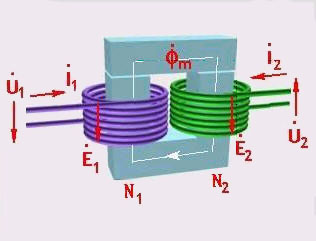
According to the law of electromagnetic induction, the induced electromotive forces can be expressed as:
E1=4.44fN1BmS×10−4
E2=4.44fN2BmS×10−4
where:
- f is the supply frequency (Hz), with a standard frequency of 50 Hz;
- N1 is the number of turns in the primary winding;
- N2 is the number of turns in the secondary winding;
- Bm is the maximum magnetic flux density in the iron core (T);
- S is the cross-sectional area of the iron core (cm2).
From these formulas, we can derive:E1/E2= N1/ N2
This shows that the ratio of the induced EMFs in the primary and secondary windings is equal to the ratio of the number of turns in the windings.
Since the leakage reactance and resistance of the primary and secondary windings are relatively small and can be neglected, we can approximate that: E1=U1, E2=U2
Thus, we have: U1/U2≈E1/E2= N1/ N2=K
where K is the transformation ratio of the transformer.
The different numbers of turns in the primary and secondary windings result in different voltages. Clearly, the side with more turns will have a higher voltage, while the side with fewer turns will have a lower voltage. This is the fundamental reason why transformers can change the voltage.
Under the influence of the currents I1 and I2 in the primary and secondary windings, the total magnetomotive force in the iron core is: I1N1+I2N2=IoN1
where Io is the no-load excitation current of the transformer.
Since IoI_oIo is relatively small (usually not exceeding 3%-5% of the rated current), it can be approximately neglected, simplifying the equation to: I1N1+I2N2≈0
Therefore, we can derive:
I1N1=−I2N2
I2/I1= N1/ N2=K
This indicates that the current ratio in the primary and secondary windings is inversely proportional to the ratio of the number of turns. In other words, the side with more turns has a smaller current, and the side with fewer turns has a larger current. Similarly, the side with a higher voltage has a smaller current, and the side with a lower voltage has a larger current.
2. Transformer Structure and Core Construction
The basic structure of a power transformer consists of an iron core, windings, live parts, and insulating parts. To ensure the safe and reliable operation of the transformer, additional components such as an oil tank, cooling device, protection device, and outgoing device are also required.
The structural composition is as follows:
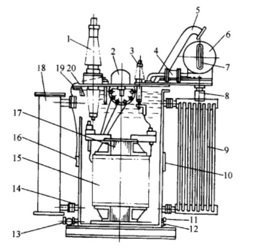
Power Transformer Structural Diagram
- High Voltage Bushing
- Tap Changer
- Low Voltage Bushing
- Gas Relay
- Safety Vent (Explosion-proof Tube)
- Oil Conservator (commonly known as Oil Tank)
- Oil Level Indicator
- Silica Gel Breather (commonly known as Breather)
- Radiator
- Nameplate
- Grounding Terminal
- Oil Sampling Valve
- Oil Drain Valve
- Manhole
- Winding (Coil)
- Signal Thermometer
- Iron Core
- Oil Pump
- Oil Tank
- Transformer Oil
Transformer
- Core Structure:
- Iron Core
- Windings
- Insulation
- Lead Wires (including tap changers, lead accessories, etc.)
- Oil Tank Body:
- Oil Tank Body
- Accessories (including oil valves, small cars, etc.)
- Cooling Device:
- (including radiators and coolers)
- Protection Devices:
- (including oil conservator, breather, oil pump, measurement components, gas relay, safety vent, etc.)
- Outgoing Device:
- (including bushings, etc.)
The iron core and windings (along with their insulation and lead wires) are collectively referred to as the transformer body or core assembly. This is the heart of the transformer and its most fundamental component. Below is a brief description of the main components of a power transformer and their functions.

Structural Diagram of Power Transformer Core Assembly
- Horizontal Insulation
- Lower Yoke Insulation
- Pressure Plate
- Insulating Paper
- Pressure Nail
- Square Iron
- Static Ring
- Corner Ring
- Iron Yoke
- Upper Clamping Piece
- Upper Clamping Piece Insulation
- High Voltage Winding
- Phase Barrier Plate
- Insulation Cylinder
- Oil Barrier Strip
- Iron Core Column
- Lower Clamping Piece Cover Plate
- Iron Yoke Insulation
- Lower Clamping Piece Support
- Low Voltage Winding
- Lower Clamping Piece Cover Plate
- Lower Clamping Piece Reinforcement
(a) Iron Core
Based on the core configuration, transformers can be divided into two types: core-type (internal iron core) and shell-type (external iron core). In a core-type transformer, the windings surround the iron core, while in a shell-type transformer, the iron core surrounds the windings. The part of the transformer that the windings encircle is called the core column, and the part that connects the core columns is called the yoke. To reduce height and facilitate transportation, large-capacity transformers often use a three-phase, five-column core structure. In this structure, the cross-sectional area of the yoke can be reduced, which also allows the height of the core columns to be lowered.
- Iron Core MaterialsThe materials used for transformer cores mainly include iron sheets, low-silicon sheets, and high-silicon sheets. Because the magnetic flux within the transformer core is alternating, it results in hysteresis loss and eddy current loss. To minimize these losses, transformer cores are typically made from silicon steel sheets that contain 5% silicon and are 0.35mm or 0.5mm thick. These sheets are punched and then stacked. The surfaces of the silicon steel sheets are coated with an insulating varnish (which is thin) and baked.The quality of the transformer is closely related to the quality of the silicon steel sheets used. The quality of the silicon steel sheet is usually expressed by its magnetic flux density BBB. Generally, the BBB value for black iron sheets ranges from 6000 to 8000, for low-silicon sheets from 9000 to 11000, and for high-silicon sheets from 12000 to 16000.
- Iron Core AssemblyThere are two methods of assembling the core: stacked assembly and butt assembly. Although butt assembly is convenient, it increases the excitation current of the transformer and does not offer good mechanical strength, which is why it is generally no longer used. The stacked assembly method involves overlapping the steel sheets of the core columns and yokes in a staggered manner, with each layer’s joints covered by the sheets of the neighboring layers. This method results in smaller air gaps in the assembled core. These joints are called direct seams and are suitable for hot-rolled silicon steel sheets.
- Iron Core GroundingTo prevent the transformer from experiencing ground discharge due to floating potential on the core or other metal components caused by electrostatic induction during operation or testing, the core and all its components (except for the through-core bolts) must be reliably grounded. Since the insulation resistance between the laminated sheets of the core is relatively low, grounding one sheet can be considered as grounding all the sheets. The core laminations are only allowed to have a single grounding point. If there are two or more grounding points, a closed loop may form between the grounding points. When the main magnetic flux passes through this closed loop, it can generate circulating currents, leading to local overheating incidents.
(b) Windings
The materials commonly used for winding transformers include enameled wire, sand-covered wire, and silk-covered wire, with enameled wire being the most commonly used. The requirements for the wire include good electrical conductivity, an insulating varnish layer with sufficient heat resistance, and some degree of corrosion resistance. Typically, high-strength polyester enameled wire of the Q2 type is preferred.
The winding is the electrical circuit part of the transformer, usually made by winding insulated copper or aluminum wire. The winding with more turns is called the high-voltage winding, while the one with fewer turns is called the low-voltage winding. Depending on the arrangement of the high-voltage and low-voltage windings relative to each other, windings can be classified into two types: concentric and interleaved.
- Concentric Windings: In this type, the primary and secondary windings are wound into cylindrical coils with different diameters and are placed on the core column, separated by an insulating paper tube between the high-voltage and low-voltage windings. Typically, the high-voltage winding is placed on the outside to facilitate insulation and to allow for the connection of the high-voltage winding’s tap lead. Concentric windings have a simple structure and are easy to wind, which is why they are widely used. Depending on the winding method, concentric windings can be further divided into cylindrical, helical, continuous, and disc types.
- Interleaved Windings: In this type, the primary and secondary windings are wound in a specific alternating sequence on the core column. This design creates more gaps between the high-voltage and low-voltage windings, making the insulation more complex and increasing the amount of wrapping work required. However, its advantages include higher mechanical strength, easier arrangement and welding of lead wires, and lower leakage reactance. Therefore, interleaved windings are often used in low-voltage, high-current transformers, such as furnace transformers and welding transformers.
(c) Insulation
- Insulation GradesInsulation materials are classified into seven grades based on their heat resistance, with each grade having a different maximum allowable temperature. Generally, all insulation materials should be able to operate for a long time (typically 15-20 years) at the temperature specified by their heat resistance grade, ensuring the reliability of the insulation in motors or electrical devices and preventing faults during operation.Common insulation materials for each grade include:
- Y Grade Insulation Materials: Cotton yarn, natural silk, woven fabrics based on regenerated cellulose, cellulose paper, cardboard, wood-based boards, etc.
- A Grade Insulation Materials: Textile products made from cotton yarn, natural silk, and regenerated cellulose that have been impregnated with liquid insulation materials resistant to high temperatures, as well as impregnated paper, cardboard, and wood-based boards.
- E Grade Insulation Materials: Polyester film and its fibers, etc.
- B Grade Insulation Materials: Materials based on mica sheets and mica powder paper.
- F Grade Insulation Materials: Glass fiber and asbestos, as well as laminated products based on these materials.
- H Grade Insulation Materials: Glass cloth and glass lacquer tubes impregnated with heat-resistant organic silicone varnish.
- C Grade Insulation Materials: Glass, electrical porcelain, quartz, etc.
Pure transformer oil has an electrical strength of 200-250 kV/cm, which is 4-7 times higher than that of air. Therefore, using transformer oil as an insulation medium can significantly reduce the size of the transformer. In addition, oil has a high specific heat and good fluidity, allowing it to dissipate heat through convection, thereby also serving as a cooling medium.
- Insulation StructureTransformer insulation is divided into external insulation and internal insulation:
- External Insulation: This refers to the insulation outside the oil tank, primarily consisting of the porcelain bushings for the primary and secondary winding leads. These bushings provide insulation between phases and between the phases and the ground.
- Internal Insulation: This refers to the insulation inside the oil tank, mainly including the insulation of the windings, the internal lead insulation, and the insulation of the tap changer, among others.
Winding insulation can be further classified into main insulation and longitudinal insulation:
- Main Insulation: This refers to the insulation between windings, between the windings and the core, and between the windings and the oil tank.
- Longitudinal Insulation: This refers to the insulation between turns and layers within the same winding.
Transformer Insulation Diagram
- Internal Insulation:
- Winding Insulation:
- Main Winding Insulation:
- High-voltage winding insulation, insulation between winding and ground (core, oil tank);
- Insulation between phases;
- Insulation of leads and other components;
- Insulation of tap changer leads and other components.
- Longitudinal Insulation:
- Insulation between different points within the same winding, such as between turns, between layers, between the core and the winding, and between the winding and the protective structure;
- Insulation of leads within the same winding;
- Insulation between different points of the tap changer.
- Main Winding Insulation:
- Lead and Tap Changer Insulation
- Insulation within the Sleeve (including the oil discharge pipe under the sleeve)
- Winding Insulation:
- External Insulation:
- Sleeve Insulation Flashover and Terminal Clearance
- Air Gaps
This diagram outlines the different types of insulation required within and outside the transformer to ensure safe and effective operation.
(d) Leads and Voltage Regulation Devices
- Leads
Leads are the wires that connect various windings, connect the windings to the bushings, and connect the windings to the tap changer. Since leads need to be drawn out from inside the windings, they must pass between the windings and through the space between the windings and the iron core or the oil tank walls. Therefore, it is essential to ensure that the leads maintain sufficient insulation distance from these parts. If these distances need to be reduced, the thickness of the lead insulation should be increased. To prevent surface discharge along the insulation junctions, the junctions should be shaped into a conical surface to lengthen the surface discharge path. When leads encounter sharp-edged electrodes (such as the screws of the iron yoke), besides maintaining a certain insulation distance, metal shielding can be used to make the electric field more uniform, thus improving the electric field distribution between the leads and sharp-edged electrodes.
- Voltage Regulation Devices
Voltage is one of the indicators of power quality, and its fluctuation range generally should not exceed ±5% of the rated voltage. To ensure that voltage fluctuations stay within a certain range, voltage regulation is necessary. One method of regulating voltage is by changing the number of turns in the transformer windings. To change the number of winding turns (usually on the high-voltage side), several taps are often drawn from the winding, which are called tap points. When the tap changer is switched to different tap points, different numbers of turns are connected. This type of voltage regulation is further divided into off-load (no-load) tap changing and on-load tap changing. Off-load tap changing refers to switching the tap points while the transformer is de-energized. The switch used for this is called an off-load tap changer (there are two at Shuangtai and Buzhuang). On-load tap changing, on the other hand, allows switching from one tap point to another without interrupting the load current, using an on-load tap changer.
2.1 On-load Tap Changing
On-load tap changing can be divided into two types: smooth regulation and stepped regulation.
Smooth regulation allows for a large, continuous adjustment of voltage but requires more material and is less efficient. The capacity is typically limited to several dozen or, at most, a few hundred kVA. It is mostly used in electrical experiments and scientific research.
Stepped on-load tap changing involves drawing several tap points from the transformer winding and using an on-load tap changer to switch from one tap point to another without interrupting the load current. This changes the effective number of winding turns. Transformers using this type of regulation consume less material and do not significantly increase in size, allowing for the production of high-voltage and large-capacity transformers.
The switching process requires a transition circuit, which can be either inductive or resistive. Inductive on-load tap changers are no longer produced due to their large size, high material consumption, and severe contact erosion. The focus here is on resistive tap changers.
The resistive type is characterized by a short transition time, with a circulating current power factor of 1. The electrical lifespan of the switching contact can be increased from 10,000-20,000 cycles for the inductive type to 100,000-200,000 cycles. However, because the resistor operates only briefly, the operation mechanism must complete the switching process without interruption. If the mechanism is unreliable and halts in the transition position, the resistor could burn out and cause an accident. With well-designed mechanisms and high-quality materials, this problem can be resolved.
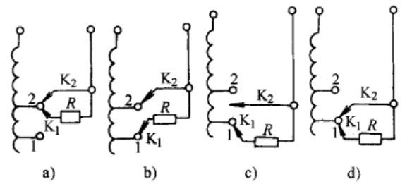
A simple circuit diagram for on-load tap changing is shown in picture. In picture, both contacts K1 and K2 of the tap changer are in contact with tap 2, and the load current is output through tap 2. The resistor RRR in series with contact K1 serves as a current-limiting resistor. In Figure 2-5b, contact K1 has switched to tap 1, while the load current is still output through tap 2. Resistor RRR limits the circulating current. Without the current-limiting resistor, the winding between taps 1 and 2 would be short-circuited by contacts K1 and K2, causing a large short-circuit current. In picture, contact K2 has moved away from tap 2 but has not yet reached tap 1, and the load current is output through contact K1 via tap 1. In Figure 2-5d, contact K2 has switched to tap 1, completing the entire switching process. The current originally output through tap 2 is now output through tap 1, all without interrupting the power supply during the switching process.
In cases of low current and low voltage per step, the switching contact can directly switch between various tap points in sequence, known as “direct switching” on-load tap changers. These are also called “composite” or “monoblock” on-load tap changers. In this type of switch, all tap contacts must handle the task of breaking the current, so the contacts need to be embedded with arc-resistant copper-tungsten alloy. This type of switch is unsuitable for large capacity or high-voltage applications. To address this issue, the task of switching the current is typically assigned to a separate switching mechanism, called the selector switch.
An on-load tap changer typically consists of a selector switch, a switching mechanism, and an operating mechanism. The switching mechanism specifically handles the switching of load current, and its actions are completed rapidly through a fast-acting mechanism according to a specific sequence. The selector switch connects the neighboring tap contacts that are about to be switched, taking on the role of continuous load carrying. Its operation is conducted without current. The operating mechanism provides the power to actuate the main switch body, which can be either motor-driven or manually operated. Additionally, it includes necessary auxiliary devices such as limiters, safety interlocks, position indicators, counters, and signal generators. An on-load tap changer is shown in picture.
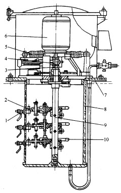
- Movable Contact
- Fixed Contact
- Bevel Gear
- Shaft
- Spring
- Motor
- Tap Changer Cover
- Insulating Cylinder
- Selector Shaft
- Limiting Resistor
This diagram appears to be a detailed view of an on-load tap changer mechanism, showing the components involved in the tap-changing process.
3. Transformer Oil Tank and Other Devices
In the structure of a power transformer, apart from the core assembly (the essential part), there are also the oil tank and other devices, without which the transformer cannot operate normally.
(a) Oil Tank and Cooling Devices
The cooling methods for oil-immersed power transformers can be classified into three types based on their capacity: oil-immersed self-cooling, oil-immersed air-cooling, and forced oil circulation (either air-cooling or water-cooling). When a transformer operates, it experiences energy losses, which are converted into heat. This heat is dissipated into the atmosphere through the surface of the oil tank and other cooling devices.
(b) Transformer Protection Devices
- Oil Conservator (Oil Cushion) and Breather (Dehydrator)The oil conservator is a cylindrical container made of steel plates, horizontally mounted on the transformer’s oil tank cover and connected to the tank via a curved pipe. One end of the oil conservator is equipped with a glass oil level indicator (oil gauge). The volume of the oil conservator is generally 8%-10% of the transformer’s total oil volume. As the oil temperature changes, the volume of transformer oil expands or contracts, and the oil conservator acts as a reservoir and replenishment system. Without an oil conservator, the oil level in the tank would be below the tank cover, and as the temperature changes, the oil level in the tank would fluctuate, causing the tank to expel or absorb air, leading to moisture and oxidation of the oil. This would reduce the electrical strength of the oil and the insulating materials immersed in it. With an oil conservator, the oil level in the conservator is much smaller than that in the tank, reducing the contact area between the oil and air, thus minimizing the chances of moisture absorption and oxidation. Moreover, the temperature of the oil in the conservator is much lower than that of the oil in the upper part of the tank, slowing down the oxidation process. Since there is little convective circulation between the oil in the conservator and the oil in the tank, most of the moisture absorbed from the air will settle in the conservator’s sediment collector (dirt box) and not enter the tank. Additionally, the installation of an oil conservator allows for the installation of a gas relay.To prevent moisture in the air from entering the oil in the conservator, the conservator is connected to the outside air through a breather (also known as a dehydrator). The breather contains a moisture-absorbing material (usually silica gel). After being impregnated with cobalt chloride, this silica gel is called color-changing silica gel, which appears blue when dry and gradually turns light red as it absorbs moisture, indicating that it has lost its moisture-absorbing effectiveness. If the moisture-absorbed silica gel is baked at 108°C for 10 hours, the moisture will evaporate, and the silica gel will return to its blue color, regaining its moisture-absorbing capability.
- Explosion Vent (Safety Vent)The explosion vent is installed on the cover of the transformer oil tank and acts as a protection device in case of excessive internal pressure due to a fault in the oil tank, which is why it is also called a safety duct. All oil-immersed transformers with a capacity of 800 kVA and above should have this device. The main body of the explosion vent is an elongated steel cylinder with a bakelite or glass diaphragm at the top. If a fault occurs inside the transformer, the pressure in the oil tank will increase. When it reaches a certain level, the transformer oil and the gases generated will burst through the diaphragm and vent outside, thereby relieving the pressure inside the oil tank and preventing the tank from exploding or deforming.
- ThermometersThe oil temperature of a transformer reflects its operational status, so it needs to be measured and monitored. The temperature measurement point is generally placed in the upper layer of the oil, measuring the top oil temperature inside the tank. Commonly used thermometers include mercury thermometers, gas thermometers, and resistance thermometers. The standard for temperature rise in Chinese transformers is based on an ambient temperature of 40°C, so the top oil temperature should generally not exceed 40°C + 55°C = 95°C. If the top oil temperature exceeds 95°C, the internal coil temperature will exceed the thermal strength of the coil insulation. To prevent the insulation from aging too quickly, it is required that the top oil temperature be monitored and controlled to stay below 85°C.
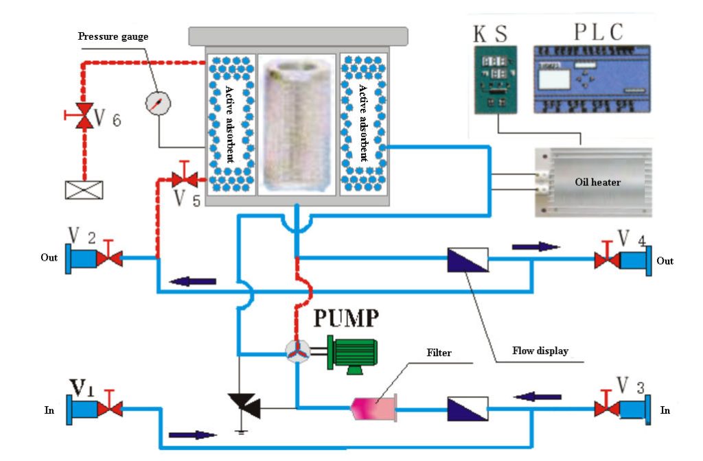
- Oil PurifierAlso known as a temperature difference filter, the oil purifier is a device used to improve the performance of transformer oil during operation and prevent further aging of the oil. When oil comes into contact with the adsorbent, moisture, debris, acids, and oxidized materials are absorbed by the adsorbent, keeping the oil clean and extending its service life. An online oil purification device is shown in picture.
- Gas Relay (Buchholz Relay)Installed on the connecting pipe between the oil tank and the oil conservator, the gas relay serves as a protection device for internal faults during transformer operation. Regulations require that all oil-immersed transformers with a capacity of 800 kVA or above, and plant transformers with a capacity of 400 kVA or above, be equipped with this device. Its function is to send an alarm signal to the operator or disconnect the power supply when the oil level drops or an internal short-circuit fault occurs, accompanied by gas generation, thus protecting the transformer and preventing the fault from worsening.
(c) Transformer Bushing
The bushing of a transformer is an insulating device that leads the high and low voltage leads of the transformer windings out of the oil tank. It provides insulation between the lead and the ground (the casing) and also secures the lead. There are various types of transformer bushings, including pure porcelain bushings, oil-filled bushings, and capacitive bushings. Solid porcelain bushings are used for voltages below 1 kV, hollow gas-filled or oil-filled bushings for 10-35 kV, and capacitive bushings and oil-filled bushings for 110 kV and above. To increase the external surface discharge distance, the bushing is designed with multi-stage umbrella-shaped skirts. The higher the voltage level, the more stages there are.
Transformer Nameplate and Technical Parameters
The nameplate on a transformer specifies the characteristics, rated technical parameters, and usage conditions of each transformer, as defined by the manufacturer. Operating the transformer according to the values specified on the nameplate is known as “rated operation.” The nameplate is the primary reference for selecting and using a transformer. According to national standards, the nameplate of a power transformer should include the following information:
(a) Model
The transformer model consists of two parts. The first part is made up of Chinese pinyin letters representing the transformer’s category, structural features, and usage. The second part consists of numbers representing the product’s capacity (in kVA) and the voltage level of the high-voltage winding (in kV).
The meanings of the Chinese pinyin letters are as follows:
- Part 1 (Phase Number):
- D—Single-phase (or Forced Directional)
- S—Three-phase
- Part 2 (Cooling Method):
- J—Oil-immersed self-cooling
- F—Oil-immersed air-cooling
- FP—Forced oil circulation air-cooling
- SP—Forced oil circulation water-cooling
- Part 3 (Voltage Levels):
- S—Three-level voltage
- Absence of S indicates two-level voltage
- Others:
- O—Fully insulated
- L—Aluminum coil or lightning protection
- O—Autotransformer (when at the beginning, it indicates step-down autotransformer; when at the end, it indicates step-up autotransformer)
- Z—On-load tap changing
- TH—Tropical (protection type code)
- TA—Dry tropical (protection type code)
(b) Phase Number and Rated Frequency
Transformers are either single-phase or three-phase. Generally, three-phase transformers are manufactured to directly meet transmission and distribution requirements. Small transformers may be made as single-phase units, and very large transformers may be made as single-phase units to form a three-phase transformer set to meet transportation requirements.
The rated frequency of the transformer is the operating frequency for which it was designed. In China, this frequency is specified as 50 Hz (commonly referred to as “power frequency”).
(c) Rated Capacity (SN)
Rated capacity is the guaranteed apparent power output by the transformer under rated operating conditions (i.e., at rated voltage, rated frequency, and rated usage conditions) as specified by the manufacturer. It is denoted as SN. For a three-phase transformer, the rated capacity is the sum of the capacities of the three phases. For a dual-winding transformer, the rated capacity is expressed as the capacity of each winding (the capacities of the windings on both sides of a dual-winding transformer are equal). For a three-winding transformer, the capacity of the medium or low-voltage winding can be 50% or 66.7% of SN (or one of them can be 100%). Thus, rated capacity typically refers to the capacity of the high-voltage winding. If the transformer capacity changes due to the cooling method, then the rated capacity refers to its maximum capacity.
(d) Rated Voltage (UN)
The rated voltage of a transformer is the rated voltage of each winding, referring to the voltage applied under rated conditions or the voltage generated under no-load conditions. The primary rated voltage U1NU_{1N}U1N refers to the rated voltage applied to the primary winding terminals of the transformer. The secondary rated voltage U2NU_{2N}U2N refers to the voltage of the secondary winding when the primary winding is connected to the rated voltage and the tap changer is set to the rated tap position, with the transformer under no load (expressed in V or kV). For a three-phase transformer, the rated voltage refers to the line voltage.
In general, appropriate taps are drawn from the high-voltage winding because the high-voltage winding, or its separate voltage regulation winding, is often placed on the outermost layer, making it easy to draw the taps. Additionally, since the high-voltage side has a smaller current, the cross-section of the lead wires and tap changer’s current-carrying components is smaller, making it easier to solve the contact issues of the tap changer. If it is a step-up transformer, the voltage regulation is done on the secondary side, in which case the magnetic flux remains unchanged for constant magnetic flux regulation. For a step-down transformer, voltage regulation is done on the primary side, where the magnetic flux changes, so it is variable magnetic flux regulation.
When the power supply voltage of a step-down transformer is not at the rated value, the low-voltage side voltage can be adjusted by connecting the tap changer on the high-voltage side to different positions. This adjustment is expressed as the percentage deviation between the tap voltage and the rated voltage. For example, if the high-voltage winding of a 35 kV transformer is U=35,000±5% V, there are three adjustment positions: -5%, ±0%, +5%. If U=35,000±2×2.5% V, there are five adjustment positions: -5%, -2.5%, ±0%, +2.5%, +5%.
(e) Rated Current (I1, I2)
The rated current of the primary and secondary windings of a transformer is the line current that the windings can allow to pass through continuously without exceeding the temperature limits under rated voltage and rated ambient temperature. It is expressed in amperes (A). In other words, it is the current calculated by dividing the rated capacity of the winding by the rated voltage of that winding, considering the appropriate phase coefficient (1 for single-phase, and √3 for three-phase). Therefore, the rated current of the transformer is the rated current of each winding and is evidently the line current expressed in effective value. If it is a single-phase transformer forming part of a three-phase group with delta-connected windings, the rated current of the winding is the line current divided by √3.
(f) Impedance Voltage (Short-Circuit Impedance)
Impedance voltage, also known as short-circuit voltage (Uz%), represents the voltage loss (in percentage) that occurs across the transformer’s impedance when it is passing rated current. The method for determining this value experimentally involves short-circuiting the secondary winding and gradually applying voltage to the primary winding until the rated current flows through the secondary winding. The percentage ratio of the applied voltage Uz to the rated voltage Un is the impedance voltage: Uz%=(Uz/Un)×100%. The percentage value of short-circuit impedance is an important parameter for the transformer as it indicates the size of the transformer’s internal impedance, i.e., the impedance voltage drop of the transformer when operating under rated load. It is crucial for determining the magnitude of the short-circuit current when a short circuit occurs on the secondary side of the transformer.
Additionally, whether two transformers can operate in parallel depends, in part, on having equal impedance voltages. Impedance voltage is also needed when calculating the short-circuit current in a power system. If the impedance voltage is too high, it increases the transformer’s own voltage loss and the cost. Conversely, if the impedance voltage is too low, the short-circuit current at the transformer’s output will be too large, requiring the transformer and the primary circuit equipment to have a higher capacity to withstand short-circuit currents. Therefore, when selecting a transformer, careful consideration should be given to the short-circuit voltage value, which is generally designed to be slightly higher as the transformer’s capacity increases.
(g) No-Load Current (I0)
No-load operation occurs when the primary winding is energized with rated voltage (at the rated frequency) while the secondary winding is open. The current that flows through the primary winding under this condition is called the no-load current. It is primarily used to produce magnetic flux and balance the externally applied voltage, so the no-load current can be regarded as the magnetizing current. The main factors determining the no-load current are the transformer’s capacity, magnetic circuit structure, and the quality of the silicon steel sheets.
Strictly speaking, the no-load current I0 has a small active component I0a that compensates for core losses and a larger reactive component I0r used for magnetization, balancing the magnetic pressure drop in the core. The no-load current is given by I0=I0a2+I0r2 and is usually expressed as a percentage of the rated current: i0%=(I0/IN)×100%.
.No-load inrush current occurs when the transformer is energized without a load connected to the circuit, producing a large magnetizing current due to core saturation. This inrush current can be several times the rated current, often reaching 5 to 7 times the rated current.
(h) No-Load Loss (P0)
The active component I0a of the no-load current causes loss, and the active power drawn from the power source is called no-load loss P0. Ignoring the resistance loss in the primary winding during no-load operation, this loss is referred to as iron loss, as it primarily depends on the unit loss of the core material. Therefore, the no-load loss (expressed in W or kW) reflects the transformer’s (economic) performance. Measuring the size and variation of no-load loss after the transformer is put into operation can help identify whether there are defects in the core.
(i) Short-Circuit Loss (Also Called Load Loss) (Pf)
Short-circuit loss is the power drawn from the power source when the secondary winding is short-circuited, and the primary winding passes the rated current (expressed in W or kW). Load loss = the resistive loss of the largest pair of windings + additional losses. Additional losses include winding eddy current losses, circulating current losses in parallel conductors, structural losses, and lead losses. The resistive loss, also known as copper loss or copper consumption, means that short-circuit loss is also called copper loss.
No-load loss is independent of the load and occurs as soon as the transformer is energized. Load loss, however, is related to the load size, and the load loss parameter is the rated value, which represents the loss occurring when rated current flows.
(j) Connection Group
This parameter indicates the connection method of each phase winding of the transformer and the phase relationship between the primary and secondary line voltages. The sequence of symbols from left to right represents the connection method of the primary and secondary windings, while the number represents the winding connection group number. Generally, high-voltage transformers are connected in Yn, Y,d11 configuration. In the transformer’s connection group, “Yn” indicates a star connection with a neutral point on the primary side (Y represents star, n indicates neutral point); “d” represents a delta connection on the secondary side. “11” indicates that the line voltage Uab on the secondary side lags the line voltage UAB on the primary side by 330 degrees (or leads by 30 degrees).
Why is the low-voltage side connected in a delta configuration? The low-voltage side is usually the load side, and a delta connection can suppress the third harmonic, preventing a large amount of harmonics from being fed back into the system and causing voltage waveform distortion. A significant characteristic of the third harmonic is that it has the same phase, which can form a circulating current in the delta side, effectively weakening the harmonics from being fed back into the system.
(k) Cooling Method
This parameter indicates the cooling medium and circulation method inside and outside the winding and tank shell. The cooling method is typically represented by 2 or 4 letter codes, indicating the cooling medium and its circulation type for the coil and the external cooling medium and its circulation type. The cooling method symbols are shown in Table.
| Cooling Method | Symbol | Application Scope |
|---|---|---|
| Dry Type Self-Cooling | AN | Generally used for small capacity dry-type transformers |
| Dry Type Air-Cooling | AF | Used for dry-type transformers with coil ducts and air channels, supplemented by cooling fans to improve heat dissipation efficiency, particularly economical for transformers with a capacity of 500 kVA or above |
| Oil-Immersed Self-Cooling | ONAN | Used for transformers with a capacity of less than 6300 kVA. Simple maintenance |
| Oil-Immersed Air-Cooling | ONAF | Used for transformers with a capacity between 8000 kVA and 31500 kVA |
| Forced Oil Air-Cooling | OFAF | Used for high-voltage large transformers |
| Forced Oil Water-Cooling | OFWF | Used for high-voltage large transformers |
Note: The symbols for forced oil-directed air-cooling or water-cooling are ODAF or ODWF, respectively.
(l) Usage Conditions
These refer to the environmental conditions specified by the manufacturer for the installation and use of the transformer. Examples include whether the transformer is intended for indoor or outdoor use, altitude, tropical or humid environments, etc. For instance, areas above an altitude of 1000 meters are considered high-altitude regions, where insulation needs to be reinforced.
