
The Transformer Turn Ratio (TTR) test is a critical diagnostic procedure used to verify the voltage ratio, phase angle, and polarity of transformer windings. Using the specific “Transformer turn ratio tester” detailed in the manual, the process involves strict safety protocols, digital parameter setup, and precise wiring.
1. Safety Prerequisites
Before touching the instrument or the transformer, you must ensure the following safety conditions are met to prevent injury or equipment damage:
- Power Outage: Ensure the equipment under test is in a complete power outage state.
- Grounding: The instrument shell must be grounded via the grounding post. The manual explicitly states that while the instrument must be grounded, the specific test terminals on the transformer itself cannot be grounded during measurement.
- Inspection: Do not use the device if the cover or panel is removed, or if the test leads are damaged.
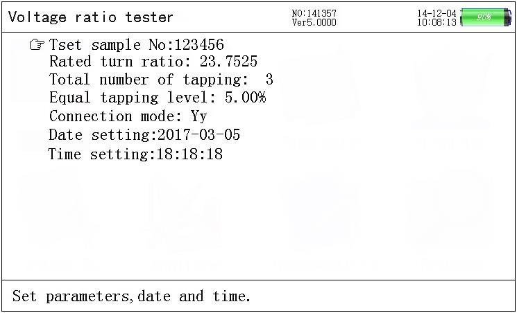
2. Parameter Setting
Before connecting the wires, you must configure the tester for the specific transformer you are analyzing.
- Power On: Start the tester to view the Main Menu.
- Enter Settings: Select the “Parameter setting” option and press “Enter.”
- Input Data: Using the arrow keys and keypad, input the following:
- Testing Sample No.: An identifier for the transformer (up to 6 digits).
- Rated TTR: The expected voltage turns ratio at the rated gear for HV and LV sides.
- Equal Tapping Level: The voltage percentage regulated at each gear.
- Tapping Amount: The total number of tapping positions.
- Exit: Once set, press “Exit” to return to the main interface.
3. Wiring Connections
The connection method changes based on the type of transformer being tested. The instrument uses a color-coded wiring harness (Yellow, Green, Red, and sometimes Black).
A. Three-Phase Transformer
- HV Side (High Voltage): Connect the Yellow, Green, and Red wires to transformer terminals A, B, and C respectively.
- LV Side (Low Voltage): Connect the Yellow, Green, and Red wires to transformer terminals a, b, and c respectively.

B. Single-Phase Transformer
- HV Side: Connect the Yellow and Green wires to terminals A and N (or X).
- LV Side: Connect the Yellow and Green wires to terminals a and n (or x).

C. Z-Type Transformer
- HV Side: Requires four wires. Connect Yellow, Green, Red, and Black to A, B, C, and N.
- LV Side: Connect Yellow, Green, and Red to a, b, and c.
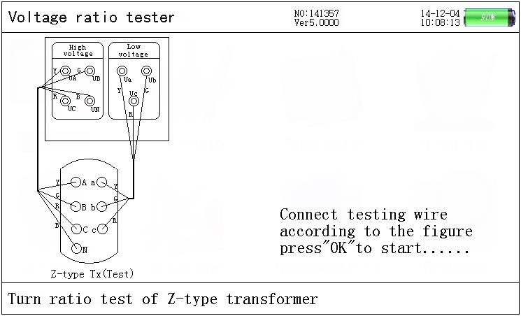
Note: Strict adherence to the wiring diagram is required. The manual warns that converse connection of high voltage and low voltage is forbidden.
4. Executing the Test
Once parameters are set and wires are connected:
- Select Test Mode: On the main menu, choose the appropriate test type (e.g., “3-phase turns ratio test,” “Single phase transformer test,” or “Z-type transformer”).
- Verify Connection: The screen will display a connection prompt diagram. Verify your physical wiring matches the screen.
- Start Test: Press “Enter” to begin the automatic test.
- The device will automatically count through a testing cycle (e.g., counting up to 40 or 57 times depending on the mode).
- The instrument automatically identifies the connecting group and shifts connection methods if using the “Blind test” function.
- Completion: The counting will cease automatically when the test is finished.
5. Interpreting Results
After the test concludes, the LCD will display the data. You should look for the following metrics:
- Voltage Values: The 3-phase voltage values for both HV and LV sides.
- Phase Angle: The measurement of the phase angle between the HV and LV sides.
- TTR Values:
- Ratio: The actual measured turns ratio.
- Error: The percentage error between the measured ratio and the rated ratio.
- Tapping: The current tapping position.
- Vector Diagram: A hexagon vector diagram is displayed on the right side of the screen. For a standard group (like zero point), the angle and direction of the HV vector (outer ring) should coincide with the LV vector (inner ring).
6. Saving and Finishing
- Save: Press the “Save” key to store the results in the history data.
- Retry: If results look incorrect, check connections and press “Enter” to test again.
- Disconnect: Only disconnect test leads after the test is complete and the machine is in a safe state. Sparks may be generated when unplugging wires due to residual charge, so exercise caution.
